How To Test Golf Cart Motor?
Power testing starts with safety and a clear rule. The spec that matters most is the main battery pack voltage, verified with a DC volt reading at the controller input. The common mistake is leaving the pack hot while you probe cables. Always switch off the cart, unplug the charger, and confirm there is no current before you touch anything.
Golf cart motor testing begins with confirming the pack voltage, inspecting wiring, and measuring current draw as you apply light throttle. With the cart off, use a multimeter on DC volts at the controller input; a healthy pack remains stable, while a sudden drop or spike points to a problem.
Safety Checklist Before Testing
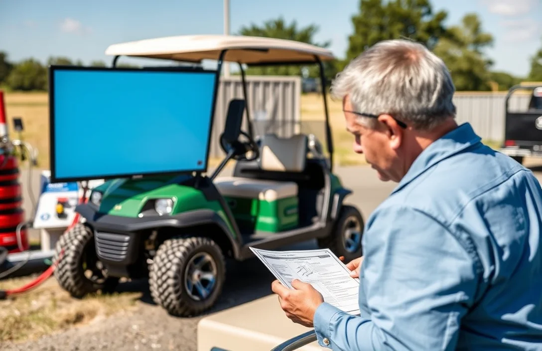
Power down the cart and disconnect the main battery. Use the lockout procedure to prevent re-energization during maintenance. If possible, verify zero voltage at the main terminals with a DC voltmeter before handling cables.
In practice, follow the manufacturer safe testing procedures step by step and document energy-off checks before performing any measurements. A written checklist helps prevent omissions when fatigue or time pressure is present.
| Component | Risk During Testing | Recommended Isolation Action |
|---|---|---|
| Main battery leads | Stored energy can re-energize | Disconnect and cap or wrap ends |
| Motor controller harness | Shorts or arcing | Disconnect harness, cover terminals |
| Drive selector and accelerator | Unintended movement | Disable controls, remove energy |
Warning: Do not perform testing while power is connected or if any high voltage parts are exposed. Ensure PPE is worn and isolation steps are complete before energizing any circuit.
Inspect Battery and Cables
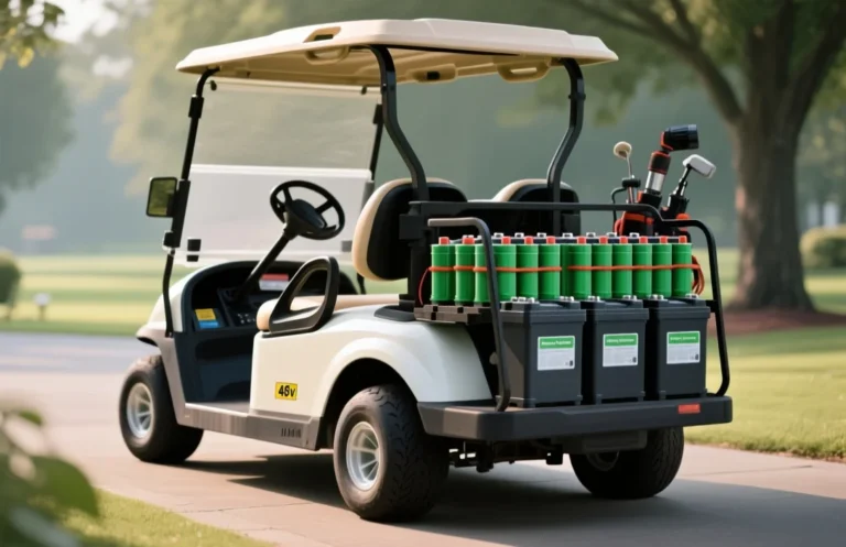
Confirm the pack is charged to baseline before testing, because a low state can mimic motor faults. Corrosion on terminals raises resistance and can hide real issues, so clean and tighten connections. Make sure the battery tray holds the pack steady to prevent movement during tests.
Use a voltmeter on the main pack terminals to read resting voltage after a brief rest. Compare to the manufacturer’s specification for your chemistry, noting that a fully charged pack sits within a target range when idle. If the reading is low, recharge and re-test after a short rest to verify stability and accuracy.
Inspect terminals for corrosion. Green, white, or blue buildup indicates oxidized connections that raise resistance and can create false fault signals during tests. Clean with a baking soda and water paste, scrub gently with a non-metal brush, rinse with clean water, and dry completely before retightening.
Inspect cables for wear. Look for cracked insulation, exposed copper, or melted jackets, especially where they bend near connections or the tray. Damaged insulation can cause shorts or intermittent faults during the motor test.
Look for swelling or leaks in the battery case. Bulges indicate gas buildup or internal damage and should halt testing until the pack is replaced. Leaks can cause chemical exposure and corrosion elsewhere in the system.
Secure the battery tray. A loose hold-down or missing strap allows movement that can stress cables during testing, causing false readings or hazard.
| Issue | What it means for testing | What to do |
|---|---|---|
| Low resting voltage | Possible low state of charge or degraded cells | Recharge and re-test after resting; confirm with two consecutive readings |
| Corrosion on terminals | Increased resistance, false fault signals | Clean, retorque, apply protective coating |
| Damaged cables | Risk of shorts or voltage drops during tests | Replace damaged sections; inspect for bends and wear |
| Swollen or leaking pack | Unsafe to test further | Isolate pack and replace promptly |
| Loose battery tray | Movement during testing causing unreliable results | Secure and torque fasteners to spec |
Check System Voltage
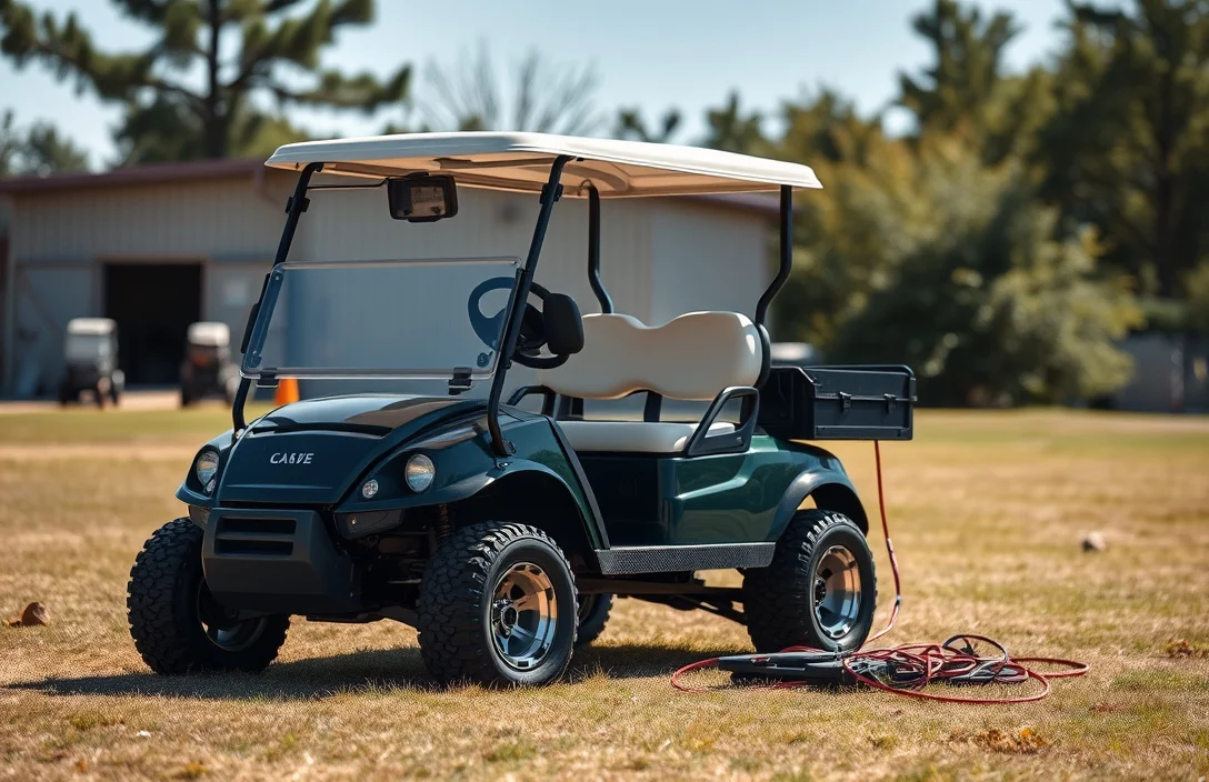
Open-circuit pack voltage should sit within the manufacturer’s specified range when the system is at rest, with no loads connected. A reading outside that range signals a charging fault, damaged cells, or loose connections that must be corrected before motor testing.
Have a digital multimeter capable of DC measurement and probes rated above the pack voltage, plus a suitably rated ammeter in series for load tests. Check the pack documentation to confirm the exact nominal value and the acceptable tolerance.
Ensure the test routine is performed on a level surface with the key removed. Record each reading and note the ambient temperature, as extreme heat or cold can affect measurements. Use a charger only for verification when instructed by the spec, not as a live power source during measurements.
| Measurement | How to Measure | What to Look For | Action if Out of Range |
|---|---|---|---|
| Open-circuit voltage | Measure across pack terminals with system off | Within the documented resting range | Recharge or diagnose cells, inspect for damaged cells |
| Harness voltage drop | Measure at controller input and battery side of main cables under no-load and light load | Small, manufacturer-specified drop | Repair or replace cables/connectors, tighten connections |
| Loaded voltage | Insert ammeter in series and engage controller at a safe speed | Voltage remains within spec under load | Investigate wiring, connectors, or controller for resistance or fault |
| Ground continuity | Ohm test from battery negative to frame and motor housing | Low, stable resistance within spec | Repair grounding path, clean contacts, re-tighten |
Safety note: Work with the system powered down, use insulated tools, and verify all handholds are dry. Avoid touching live terminals or moving parts during measurements to prevent shocks or short circuits.
With voltage within spec, you are ready to proceed to bench-testing motor signals in the following step, keeping the same emphasis on safe, controlled conditions.
Bench Test Motor Signals
Key checks during a bench test isolate the motor from load to verify windings, insulation, connectors, and sensor timing. Use a 4-wire method for resistance, a megohmmeter for insulation, visual and functional checks on connectors, and diagnostic sensing for Hall outputs before any on-cart testing. Document deviations and follow the motor manual for acceptable ranges.
On-Cart Run Test

Secure the cart on a level surface with the wheels chocked and the parking brake engaged. Clear bystanders and obstacles, then begin a controlled ramp of throttle while the drive train sees a representative load.
| Stage | Throttle | RPM | Current (A) | Voltage (V) | Observations |
|---|---|---|---|---|---|
| Idle | 0% | N/A | 0 | Nominal | Brake test ok |
| Low Load | 10 – 20% | Low rise | 5 – 15 | ~48 – 50 | Stable |
| Moderate Load | 30 – 40% | Moderate rise | 15 – 25 | ~47 – 49 | Consistent |
| High Load | 60 – 80% | High, near max | 30 – 50 | ~46 – 48 | Warm but not hot |
| Full Throttle | 100% | Max | 60 – 75 | ~45 – 47 | Monitor temperature and noises |
Note: If readings deviate beyond normal ranges, the motor or controller may need inspection, service, or replacement. Keep a log and consult the service manual before proceeding to further testing.
Safety, Heat, and Replacement Triggers
Overheating is the clearest warning sign of motor trouble in a golf cart. A motor that heats quickly under normal load or runs hotter than the controller indicates a cooling, wiring, or insulation fault that deserves inspection.
Overheating indicators include a fast rise in case temperature after start-up, frequent thermal cutoff trips by the controller, and unusual smells near the motor.
Thermal cutoff trips protect windings but repeated trips point to an underlying problem in cooling or load management.
Swelling, odors, or leaks around seals indicate insulation or bearing problems that should not be ignored.
Bearings wear or looseness create vibration, noise, and shaft play that signals impending failure.
| Symptom | What it typically indicates | Recommended action |
|---|---|---|
| Excessive heat or rapid temp rise | Overload, poor cooling, or winding stress | Pause use, inspect cooling path, verify fan and vents, consider motor service or replacement if persists |
| Burnt smell or insulation damage | Insulation breakdown or coil damage | Do not run; replace motor windings or whole motor assembly |
| Excessive shaft play or grinding | Worn bearings or misalignment | Inspect bearings, re-seat or replace as needed |
| Oil leaks around seals | Seal failure, lubrication loss | Replace seals or the motor module |
| Severe vibration under load | Rotor faults or bearing failure | Test in safe setup; replace if abnormal persists |
When any of these signs are present, plan for a proper test or professional service. Running a compromised motor risks controller damage, heat transfer to batteries, and potential fire hazards.
Quick Summary
To test a golf cart motor safely, verify voltage and controller compatibility, then follow a controlled, manual test.
Frequently Asked Questions
How can I check the compatibility of my golf cart motor with the battery?
To ensure compatibility, check the voltage rating of the motor and match it with the battery’s voltage. Most golf cart motors operate at 36V or 48V, so confirm your battery fits that specification.
What should I do if my golf cart motor overheats during testing?
If the motor gets excessively hot, it may indicate a problem. Ideally, the motor should stay below 150°F during operation; if it exceeds this, stop testing and check for issues like poor connections or excessive load.
How long should I run a golf cart motor during a test?
A typical testing duration is around 5 to 10 minutes to assess performance without overheating. Always monitor the motor’s temperature during this time to avoid damage.
What safety precautions should I take when testing a golf cart motor?
Always wear safety goggles and gloves to protect against potential sparks or electrical shorts. Ensure the area is well-ventilated and free of flammable materials before starting the test.
What common mistakes should I avoid when testing a golf cart motor?
A common mistake is not checking the battery charge level before testing. Low battery voltage can lead to inaccurate test results and potential damage to the motor.