

How To Check Golf Cart Solenoid?
Power decision first: always disconnect the battery or main power before touching the solenoid. The spec that matters most is system voltage – 36V or 48V carts require different checks. The common mistake is testing with the power on or using the wrong meter scale. Start by locating the label on the cart that shows the pack voltage and setting your multimeter to DC volts accordingly.
Solenoid check: With power off, locate the solenoid and identify the small coil terminals. Set a multimeter to DC voltage. Have a helper press the accelerator while you measure across the small terminals; expect about 36V for 36V carts or about 48V for 48V carts when activated. If you see 0V, troubleshoot the control path.
Solenoid Purpose and Function
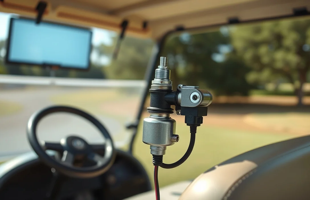
In a golf cart, the solenoid is the high-current switch that links the battery pack to the motor circuit. The coil receives a low-current control signal from the accelerator and forward-reverse module, and when energized it closes the heavy-duty contacts to let pack voltage reach the motor. The coil and the main contacts are separate components; coil health matters because a weak coil may fail to engage even with good wiring.
The solenoid’s role is to act as a bridge between power and motion. When the control circuit sends a signal, the coil pulls the contacts closed, allowing current to flow through the main path to the motor or controller. When the signal is removed, the contacts open and the motor loses power. This arrangement protects the driver circuit from high current while providing a simple, reliable method to start and stop motor current.
Tools and Safety Gear
Essential tools for testing the solenoid in a golf cart include a multimeter, socket or wrench set, and safety gloves. These tools help ensure accurate readings and safe handling during maintenance.
| Item | Amount/Specification | Notes |
|---|---|---|
| Multimeter | 1 | For measuring voltage and continuity. |
| Socket/wrench set | 1 | To remove and secure solenoid connections. |
| Screwdriver set | 1 | For opening access panels if necessary. |
| Safety gloves | 1 pair | To protect hands from sharp edges and electrical hazards. |
| Safety goggles | 1 pair | To protect eyes from debris and accidental splashes. |
Locating the Golf Cart Solenoid
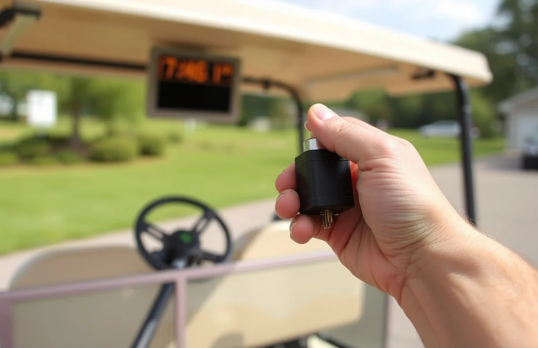
The solenoid is typically located near the battery pack, mounted on the frame of the golf cart. It can usually be found in an area that is easily accessible, allowing for straightforward troubleshooting and maintenance.
Common mounting locations include:
Model variations may affect the exact location of the solenoid:
Common models can differ in solenoid placement, so it’s essential to refer to the specific owner’s manual for accurate guidance.
In practice, some golf carts may have additional covers or panels that need to be removed to access the solenoid. Using the appropriate tools, such as a socket wrench or screwdriver, can facilitate this process.
Consider the following tips while locating the solenoid:
Identifying the correct solenoid location is essential for effective troubleshooting and maintenance. If unsure about the location, consult the cart’s service manual or seek assistance from a professional.
Pre-Test Safety Prep
Power down the cart and isolate the high energy circuit before any checks. Remove the ignition key, switch off the main power, and engage the parking brake to prevent movement. If a battery disconnect or master switch is present, actuate it and wait a few minutes for stored energy to dissipate. Use a meter to confirm zero voltage on accessible conductors before touching anything.
Lockout and tagout procedures prevent accidental re-energizing during service. Attach a lock to the disconnect or master switch and place a clearly written tag stating who locked it and the date. If a lock cannot be used, apply a sturdy tag and limit access until work is done.
Personal protective equipment and a dry, organized workspace reduce risk. Wear insulated gloves and eye protection, keep jewelry off, and stand on a non-conductive mat or dry surface. Ensure lighting is good and keep tools arranged so you won’t reach across live connections.
Tools and checks you should have ready include a digital multimeter, insulated screwdrivers, insulated pliers, a flashlight, and a non-conductive mat. Inspect test leads for wear, confirm the meter reads zero with leads shorted, and verify it is set to the correct voltage range before touching any circuit.
Warning: Never bypass safety devices or work on energized circuits. Treat any sign of damage, swelling, or heat as a stop signal and re-check energy removal before continuing.
| Action | How to perform | Why it matters |
|---|---|---|
| Zero energy check | Measure across main pack terminals with a DVOM; ensure readings are 0V. | Confirms no stored energy can arc or shock you. |
| Lockout/tagout verified | Inspect lock/tag is in place and cannot be removed by others. | Prevents accidental energizing during work. |
| PPE and environment | Don PPE and keep area dry and well lit. | Reduces risk of injury and slips or shorts. |
Test Coils and Control Signals

energize the control path and verify the coil drive on the small terminal. You should see pack voltage on the small terminal when the pedal or key signal is present, and a solid click as the solenoid pulls in. If either test fails, trace upstream through the pedal switch, Forward/Reverse wiring, and controller for faults.
Test Main Contacts and Continuity
Testing the main contacts of the solenoid involves verifying that the heavy contacts can pass current effectively. The procedure includes large-terminal checks for voltage and resistance, ensuring all connections are solid and functional.
Begin by identifying the large terminals on the solenoid, typically marked as the input and output for current. Use a multimeter to measure voltage across these terminals while the solenoid is activated. For a 36V golf cart, expect to see readings around 36 volts, while for a 48V system, readings should be close to 48 volts.
Resistance checks are also critical. After deactivating the solenoid, measure the resistance across the large terminals. A good solenoid should show very low resistance (ideally near 0 ohms). If the resistance is significantly higher (greater than 0.4 ohms), this indicates burnt or pitted contacts, necessitating replacement of the solenoid.
Common symptoms of a faulty solenoid include:
Continuity checks can further confirm solenoid functionality. With the solenoid disconnected, use the multimeter’s continuity setting to test between the large terminals. A continuous beep indicates good continuity, while no beep suggests welded contacts, necessitating immediate replacement for safety.
| Test Result | Likely Diagnosis | Action |
|---|---|---|
| No click, no voltage at small terminals | Problem upstream (pedal switch, wiring) | Troubleshoot signal path |
| Voltage at small terminals but no click | Dead coil | Replace solenoid |
| Click but high resistance (>0.4Ω) | Burnt contacts | Replace solenoid |
Using these steps ensures a comprehensive evaluation of the solenoid’s main contacts and continuity, allowing you to maintain the reliability of your golf cart’s electrical system.
Interpreting Symptoms and Fixes
Two core patterns guide diagnosis: no click or no voltage at the coil and no movement despite a click indicate upstream control issues; a solid click with movement but no drive points to worn main contacts inside the solenoid. Use voltage and continuity readings at both small coil terminals and large main terminals to confirm the path and plan the fix.
Upstream problems to inspect
Replacement considerations Practical fixes prioritize matching system voltage, coil resistance, and connector layout. OEM solenoids fit the original harness and performance, but aftermarket options can save money if they match the resistance and terminal sizes. Verify warranty terms and ensure the replacement aligns with the cart’s 36V or 48V system and with the controller’s expected load.
| Factor | What to check | Why it matters |
|---|---|---|
| Voltage system | 36V or 48V solenoid, correct coil rating | Prevents non-engagement or overheating |
| Coil resistance | Measure across small terminals; compare to spec | Out of spec can indicate a weak pull or heat buildup |
| Main contacts | Continuity across large terminals when engaged | Worn or welded contacts cause no drive |
| Harness/connectors | Inspect for corrosion, loose pins | Intermittent signals lead to misleading test results |
| Warranty/quality | OEM vs aftermarket options | Affects reliability, return policy, and long-term cost |
Safety reminder: Always disconnect the battery pack before handling cables or removing the solenoid to avoid sparks or short circuits. Use a properly rated multimeter and keep metal tools away from live bus bars.
Quick Summary
The main takeaway is to verify coil voltage and click, then inspect control wiring before replacing the solenoid.
Frequently Asked Questions
How do I check a golf cart solenoid on a 36V or 48V system to confirm it is working?
Use a multimeter to measure across the small and large terminals while the cart is activated; you should see about 36 volts on 36V carts or about 48 volts on 48V carts.
How long should a solenoid test take and what voltage should you expect at the small terminals?
A focused test typically takes about 2-5 minutes; the small terminals should read full pack voltage when activated, around 36V or 48V depending on your system.
What safety steps should you take if the solenoid or wiring gets hot during testing?
Stop testing, disconnect the battery, and let things cool; heat indicates overload or loose connections that need rechecking before continuing.
What signs during testing indicate a solenoid needs replacement rather than repair?
If you hear a click but the wheels don’t move and the resistance across the large terminals is greater than 0.4 ohms, the contacts are burnt and the solenoid should be replaced.
What buying mistakes should I avoid when selecting a replacement golf cart solenoid?
Avoid mixing 36V and 48V solenoids with the wrong cart voltage and verify the terminal layout matches your wiring so the unit fits and functions correctly.