

How To Test Golf Cart Solenoid?
Power safety comes first: disconnect the battery pack before touching any solenoid wiring. The spec that matters most is the coil resistance listed on the label, and the first setting to check is the main contact terminals for continuity when the control switch is energized. The common mistake is testing a live circuit or skipping isolation, which can spark or damage components.
Golf cart solenoid test: With the battery disconnected, measure resistance across the two large terminals; you should see a continuous circuit. Reconnect the pack, energize the control for 1-2 seconds, and listen for a solid click. If there is no click or the resistance is open, replace the solenoid.
Solenoid role in golf cart

The solenoid in a golf cart acts as an electrical switch that controls the flow of power from the batteries to the motor. It is typically located near the battery pack, often mounted on or near the motor controller. A malfunctioning solenoid can prevent the cart from starting or cause intermittent power issues.
Common signs of solenoid failure include:
Understanding the role of the solenoid is crucial for troubleshooting electrical issues in a golf cart. When testing or replacing a solenoid, it’s important to verify that all connections are secure and that the solenoid itself is compatible with the specific golf cart model. Regular checks can help prevent unexpected failures during operation.
Safety and prep steps
Powering down and isolating the battery is essential before testing any component in a golf cart, including the solenoid. Disconnect the battery cables, starting with the negative terminal to prevent any accidental short circuits. Ensure that the area around the battery is clear of any flammable materials to maintain a safe working environment.
Following these safety and preparation steps will help ensure a smooth testing process and enhance your overall safety while working on the golf cart’s electrical system.
Essential testing tools
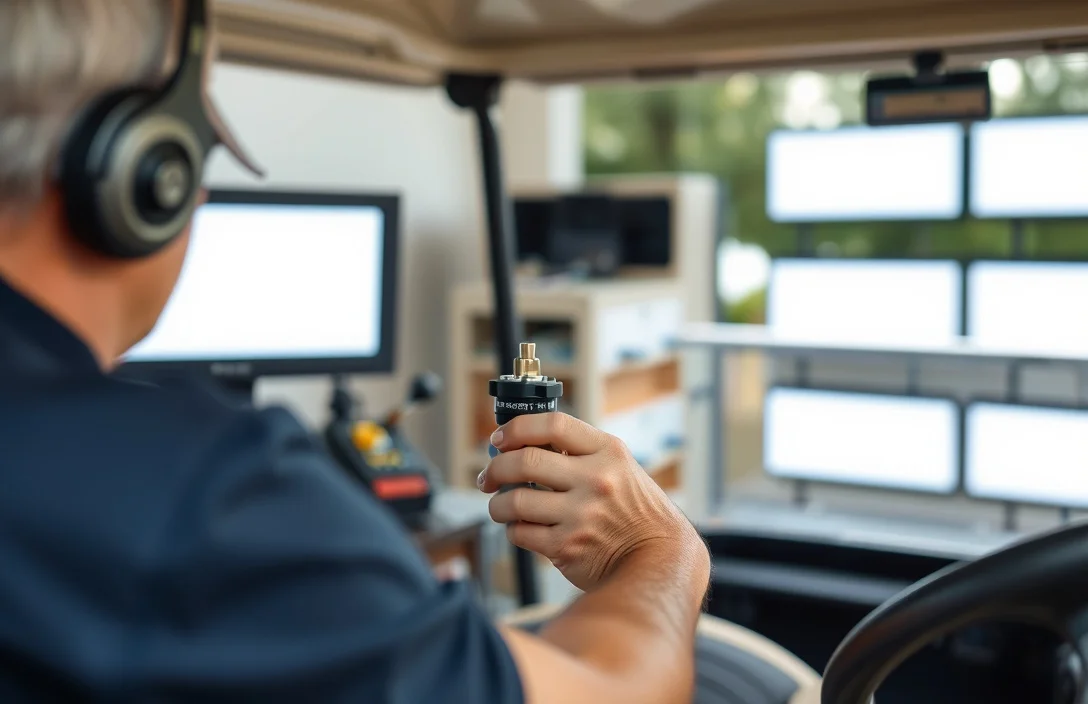
A digital multimeter is essential to verify solenoid coil resistance and actuator continuity. A bench power supply in the 12 to 48 V range lets you energize the solenoid safely for controlled testing, while a current-capable meter helps confirm draw at actuation. Use the service manual to match expected coil resistance and terminal layout, and wear proper PPE during testing.
| Item | Amount/Specification | Notes |
|---|---|---|
| Digital Multimeter | Auto-ranging or manual; resistance range down to 0.1 ohm; continuity and DC voltage | Measure coil resistance across solenoid terminals with the coil disconnected from cart wiring; compare to the service manual spec within tolerance. |
| Bench Power Supply | 12 – 48 V DC; current capability 5 – 10 A; adjustable with current limit | Energize the solenoid by wiring through proper connectors; set current limit just above the coil’s expected current to avoid overheating. |
| Ammeter or Clamp Meter | 0 – 20 A or higher | Place in series with the solenoid circuit during energization to verify current draw; compare with manual spec. |
| Test Leads and Alligator Clips | Insulated, rated for 30 A+ | Ensure solid, clean connections; keep leads short to minimize added resistance and heat. |
| Service Manual / Model Reference | Model-specific coil spec | Confirm terminal layout, coil resistance, and safety precautions for your cart model. |
| PPE and Safety Gear | Safety glasses, insulated gloves, dielectric mat | Protect against arcs and shocks; keep area dry and tools rated for the working voltage. |
| Replacement or Known-good Solenoid (optional) | 1 spare unit | Compare readings and operation to isolate a failing solenoid versus wiring or control issues. |
Check coil resistance
Coil resistance is read with a low-range ohmmeter across the solenoid’s two small coil terminals after isolating the circuit. A correct measurement equals the value shown in the service manual; a reading far outside that spec indicates a wounded or shorted coil. If the coil reads open or dead short, replace the solenoid.
Identify coil terminals on the solenoid. Look for two small screw posts separate from the large power posts. The coil posts are often labeled S and R or plus and minus on some models; check the diagram on the unit or in the service manual. Ensure the battery is disconnected before touching these terminals.
Prepare the measurement by isolating the coil and test area. Disconnect the battery, switch off connectors, and if possible remove the solenoid from the circuit to avoid parallel paths. Set your meter to a low ohm range, then touch the probes to the two coil terminals and record the value.
Compare the reading to the specification in the manual. An open circuit means the coil is broken, and the solenoid will not energize. A reading that is abnormally low or shows a short to other paths indicates a coil short or internal insulation failure. A reading within the expected range usually means the coil is healthy, but proceed with other tests to confirm.
| Condition | What it means | What to do |
|---|---|---|
| Open circuit (infinite resistance) | Coil is broken or disconnected | Replace solenoid; recheck wiring and connections |
| Very low resistance or short | Coil windings shorted or shorted to other paths | Replace solenoid; inspect harness for damage |
| Within spec | Coil appears healthy | Continue with in-circuit tests or function check |
For example, on a 48V golf cart, you compare your measurement to the spec in the manual. If the coil reading sits within the documented range, you can move to the next test in the sequence with confidence that the coil is not the fault.
Tip: Isolate the coil from the circuit to avoid reading through other windings or wiring. If you can’t disconnect, treat the result as inconclusive and proceed to the next tests.
In-circuit voltage check

Coil voltage should appear across the solenoid terminals when the control path closes, with only small losses in wiring. With the key on and the accelerator commanded, measure across the solenoid coil terminals using a DC voltmeter or a high impedance meter. If the reading is far below the system voltage, inspect the control path for voltage drops and failing switches.
Record readings with the cart state and switch positions so you can re-check later. If coil voltage is present but the solenoid does not click, the issue is likely mechanical or in the drive circuit rather than in the in-circuit coil drive.
Bench test on a solenoid stand
Remove the solenoid from the cart safely and mount it on the solenoid stand. Use a momentary control switch to energize the coil with its rated voltage, then observe the plunger movement and contact closure.
Before wiring, disconnect the main battery or isolate the bench supply. Keep the leads short, use insulated tools, and ensure the solenoid is secured so it cannot move.
In practice, a healthy solenoid shows consistent travel and clean contact closure, with no overheating or unusual noise.
Warning: Do not energize for longer than a few seconds at a time on the bench. Use current limiting and keep hands clear of moving parts.
| Test | How to perform | Pass criteria |
|---|---|---|
| Coil resistance | Measure across coil leads with power removed | Resistance matches label or falls within a reasonable range for the coil |
| Plunger travel | Observe movement along its bore during energization | Full, smooth travel with no binding |
| Contact closure | Check continuity across output contacts while energized | Low resistance or closed circuit when energized |
| Overheating tendency | Energize briefly and monitor temperature | No hot spots or rapid temperature rise |
Record the results clearly and use them to guide the next steps in evaluation and potential replacement decisions.
Replacement triggers and verdict
Replace when the solenoid shows burned windings, melted insulation, or heavy terminal corrosion that prevents reliable engagement. A rebuild is reasonable if the coil and case are intact and only minor corrosion or wear is present. If parts are scarce or the cart is older, replacing with a known-good module often reduces downtime and uncertainty.
Quick Summary
A safe, step by step check can confirm whether the golf cart solenoid energizes and engages the starter circuit.
Frequently Asked Questions
How can I test golf cart solenoid compatibility with my controller and battery voltage?
You should verify that the solenoid coil voltage matches your cart’s system; common golf cart solenoids are 12V or 24V devices, so check the label on the solenoid or the cart service manual to confirm the voltage before testing.
How long should a golf cart solenoid test take and what heat signs indicate a problem?
A bench test should show the solenoid engaging within a second or two; if the solenoid case becomes hot to touch within 30 seconds, stop testing and inspect for a short or binding plunger.
What safety steps should I follow when testing a golf cart solenoid to prevent sparks or shocks?
Always disconnect the main battery pack before bench testing a golf cart solenoid, and use insulated tools and a dry, clear workspace to prevent shocks and shorts.
How do I know when it is time to replace a golf cart solenoid after testing?
If during testing the solenoid does not click or pull in when energized at the rated voltage, replace it; also check the coil resistance against the cart manual, as out-of-spec coil resistance indicates failure.
What common buying mistakes should I avoid when selecting a replacement solenoid for testing?
A common buying mistake is choosing a solenoid for the wrong voltage or terminal layout; ensure the replacement has the same coil voltage and terminal configuration as your original part to avoid overheating or misfit during testing.